In this post, we’ll explore electrical circuits. We’ll cover the essential question “How does electricity flow?” and break down the components of circuit diagram. Also, we’ll distinguish between series and parallel circuits. This guide aims to enhance your comprehension of these concepts through clear explanations and practical examples. Join us in this insightful journey through the circuitry!
What We Review
How Does Electricity Flow?
In order to understand how electricity flows, we need to start with the basics. Electricity is the flow of electric charge, which, in most household contexts, means the movement of electrons through a conductor. These electrons move from areas of negative charge to areas of positive charge, creating an electric current.
The Role of Electrons
In conductive materials, such as metals, some electrons are free to move. These electrons aren’t bound to any particular atom and can drift from one atom to another. When you apply a voltage, or potential difference, across the conductor, it creates an electric field. This field exerts a force on these free electrons, propelling them through the conductor. This flow of electrons is what we refer to as electricity.
Circuits
For electrons to flow, there must be a complete path, or circuit. Specifically, the circuit must lead from the negative charge source, through the conductor, and back to the positive charge source. The simplest version of this is a light bulb, a battery, a switch, and wire. If you close the switch, the circuit is complete and the battery’s negative terminal repels electrons (as like charges repel) and sends them through the wire to the bulb. As a result, the bulb lights up and the electrons continue flowing back to the positive terminal. When the switch is open, the circuit is not complete and the electricity does not flow through the wires.
Conventional vs. Electron Flow
Surprisingly, we often talk about the flow of electricity as if it were positive charges moving, and we say it flows from the positive terminal to the negative terminal. This is “conventional current” and scientists created this definition before they knew that electrons were the charges actually moving. On the other hand, “electron flow” acknowledges that electrons are moving from the negative to the positive terminal. Despite this difference, both models are appropriate, depending on the context, and they both describe how circuits behave.
Circuit Integrity
The integrity of this path is crucial. If something or someone breaks the circuit, the flow of electrons stops, and the current stops too. This could be intentional, like a switch, or something accidental, like a broken circuit element.That’s is why we call it a circuit—it’s a circle, and it has to be complete for electricity to flow.
By understanding electron movement in a circuit, you can start to understand more complex electrical concepts, for example, how different types of circuits (like series and parallel) impact this flow. The first thing to remember is that it’s all about providing a path for electrons to move from areas of high concentration to areas of low concentration, much like water flowing down a hill.
Diagramming the Flow of Electricity
It’s important to realize that electrical circuits are the foundation of modern technology. You can find them in everything from smartphones to kitchen appliances. An electrical circuit is simply a path or a loop around which an electrical current flows. The path may be closed (like a loop) or open (broken), and it might consist of various components like resistors, transistors, capacitors, wires, and other devices.
Circuit Diagrams
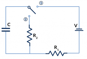
Circuit diagrams, also known as schematic diagrams, are visual representations of electrical circuits and the flow of electricity. They use simplified standard symbols to represent electrical components and lines to show the connections between those components. They are crucial for the design, construction, and maintenance of electrical and electronic equipment.
The Importance of Circuit Diagrams
Moreover, these diagrams are a universal language, meaning people from all over the world, regardless of their country or field, can understand the workings of a circuit. This common language is super handy when it comes to sharing designs, solving circuit problems, and ensuring that circuits are safe and correct.
How to Read Circuit Diagrams
To master the art of reading circuit diagrams, you need to get familiar with the symbols that represent various components. These symbols are connected by lines that illustrate the pathways between the components, essentially showing how current flows within the circuit. So, the trick is to spot the symbols and then follow the lines, which act just like virtual wires.
Circuit Symbols
When it comes to circuit symbols, think of them as a type of shorthand. They’re the little icons you see on circuit diagrams and they provide a quick way to know what components are in the circuit. They’re the key to unlocking the details of your circuit diagram.
Basic Circuit Symbols
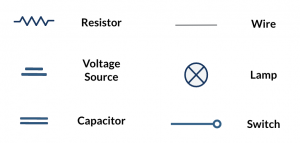
- Resistor: A rectangle or a zigzag line represents a resistor, indicating a component that resists the flow of electrical current.
- Capacitor: Two parallel lines with a gap represent a capacitor, a component that stores electrical energy.
- Voltage Source or Battery: A series of alternating short and long lines represents a battery, illustrating the power source for the circuit.
- Light Bulb: A circle with a cross inside represents a light bulb, indicating a component that emits light when current flows through it.
Advanced Circuit Symbols
As circuits get more complex, you will encounter symbols for a broader range of components, such as diodes, transistors, and more. Each symbol conveys essential characteristics of the component it represents. To see a full list of circuit symbols and what they represent, review the following post.
Learning and Using Circuit Symbols
Learning these symbols is a key step in understanding the world of electronics. They’re the language of electronics, allowing you to create or read complex circuit diagrams. Whether you’re designing a circuit, the ability to identify these symbols and understand their meanings is crucial.
How Does Electricity Flow in Different Types of Circuits?
There are two main types of electrical circuits: series and parallel circuits. They each have unique characteristics, advantages, and disadvantages.
Series Circuits
In a series circuit, components are arranged end-to-end. This allows the same current go flow through each component. If you imagine water flowing through a single pipe with several pumps along its length, you’ve got the idea of a series circuit.
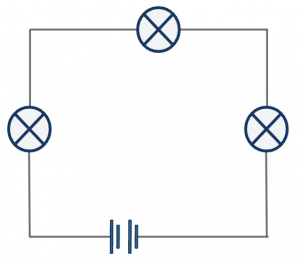
Characteristics of Series Circuits:
- Current: Identical through all components.
- Voltage: Divided across the components.
- Resistance: Total resistance is the sum of the individual resistances.
- Breaking the Circuit: If one component fails, the circuit breaks, and current ceases to flow.
Parallel Circuits
Parallel circuits have multiple paths for the current to move through, and components are arranged side by side. If you imagine several separate water pipes coming from the same source and going to the same destination, you’re thinking of a parallel circuit.
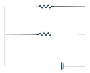
Characteristics of Parallel Circuits:
- Current: Divided through the different paths, with the total current being the sum of the currents through each path.
- Voltage: Same across all components.
- Resistance: Total resistance decreases as more paths are added.
- Continuity: If one path is disrupted, current still flows through the other paths.
Difference Between Parallel and Series Circuits
It’s crucial to recognize the differences between series and parallel circuits to understand how they operate.
Current and Voltage
In series circuits, the current is the same through all parts, but the voltage is split between them. In parallel circuits, the opposite happens: the voltage is the same for all parts, but the current divides based on the number of paths.
Resistance
Resistance in series circuits adds up, making the total resistance higher. In parallel circuits, adding more paths provides more options for the current, lowering the total resistance.
Reliability
Series circuits have a downside: if one part fails, the whole circuit stops working. But in parallel circuits, even if one path is interrupted, the current still flows through the other paths, making them more reliable.
Applications of Circuits
The choice between series and parallel circuits depends on the specific requirements of a task. We commonly use series circuits when we want to ensure a uniform current. Meanwhile, parallel circuits are preferred for their reliability and consistent voltage levels.
Quick Vocabulary Review for Circuits
Before we wrap up, let’s review some vocabulary for talking about circuits and how electricity flows.
- Voltage (V): Think of voltage as the push that gets electricity moving. It’s like the pressure that makes water flow through a pipe. In our circuits, voltage is the force that moves electric current around. It’s measured in volts (V).
- Current (I): Current is the flow of electricity. You can imagine it as the amount of water flowing through a pipe. But here, it’s the electric charge that moves in the circuit. We measure current in amperes, often shortened to amps (A).
- Resistance (R): Resistance slows down the current. The higher the resistance, the slower the electric current flows. This is measured in ohms (Ω).
- Circuit: This is a path or a loop that electricity follows.
- Conductor: Materials that let electricity flow easily, like most metals, are called conductors.
- Insulator: These materials do not allow electricity to pass through easily. Plastic and rubber are good examples.
Remembering these key terms will help you understand how circuits work. Keep this vocabulary list handy while studying, and you’ll be a circuits pro in no time!
Conclusion
In summary, we learned the basics of electrical circuits, like how electricity flows and how to read diagrams with special signs. We also reviewed two kinds of circuits, series and parallel, and learned about their differences This material goes beyond the classroom; it’s about real things like our gadgets, houses, and big places like cities. Now you know more about the electric stuff all around us!