
Electricity powers much of the world around us, from the smartphone in your pocket to the lights in your classroom. Moreover, at the heart of these technologies lies a fundamental concept: electrical circuits. These circuits are the pathways that allow electricity to flow, powering various devices and systems. In the following post, we’ll explore series circuits, one of the two main types of circuits used in electronics. But what is a series circuit? A series circuit is a simple setup where components like bulbs, resistors, or batteries are connected end-to-end, forming a single pathway for electric current to flow. Understanding series circuits is essential for anyone interested in electronics or physics, as they are the building blocks for more complex designs.
What We Review
What is a Series Circuit?
Picture a string of old-fashioned Christmas lights: when one bulb goes out, they all go out. This is a classic example of a series circuit. In a series circuit, electrical components are connected in a single, continuous loop. This means that the current (the flow of electric charge) has only one path to take. If any part of the circuit is broken or a component fails, the entire circuit stops working, just like those Christmas lights.
In contrast, a parallel circuit is one where components are connected across multiple pathways. If you’ve ever used a strip of modern LED lights, you’ve seen a parallel circuit in action. In these circuits, each component has its own direct path to the power source. If one LED burns out, the others keep shining because they have separate paths for the current to flow.

Accordingly, understanding the differences between series and parallel circuits is crucial for understanding electronics. Series circuits are simpler and have their unique characteristics and applications, which we’ll explore in more detail.
What Does a Series Circuit Look Like?
When we talk about visualizing a series circuit, think of it as a straightforward, no-detour path. For example, consider all of the components in a series circuit like dominoes in a line; the current flows through one after the other with no branches or alternative routes. This simplicity makes series circuits an excellent starting point for understanding the basics of electrical circuits.
Series Circuit Diagram
To demonstrate this concept, let us look at a basic series circuit diagram.
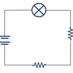
In this example, the diagram shows a battery, two resistors, and a light bulb, all connected in a single line. The battery, positioned on the left, acts as the power source. Following the battery are the two resistors, and finally, on the right is the light bulb. You’ll see straight lines connecting these components, representing wires. These illustrate the clear, linear path that the electric current follows.
What is an Advantage of a Series Circuit?
First, the primary advantage of series circuits is their simplicity in design and function. This simplicity makes them easy to construct and understand, ideal for educational purposes and basic electronic projects. In a series circuit, the current that flows through each component is the same, so diagnosing problems or calculating values like voltage and resistance becomes straightforward.
However, it’s important to note that the simplicity of series circuits also brings a limitation: if one component fails, the entire circuit stops working. This characteristic is both a pro and a con, depending on the application.
Series Circuits in Everyday Life
Series circuits may seem basic, but they find practical applications in everyday life. One of the most common examples is the string of old-fashioned lights. When one bulb burns out, the whole string goes dark, indicating a series circuit configuration.

Another example is certain types of flashlights, where multiple batteries are connected in series to provide the necessary voltage. In these flashlights, each battery adds to the total voltage, allowing the light bulb to receive enough power to shine brightly.
How to Find Current in a Series Circuit
As you saw, in a series circuit, the flow of electric current is like traffic moving along a single-lane road; it has to follow one path. This means that the current (measured in amperes, or ‘amps’) is the same at every point in a series circuit. Moreover, if you measure the current flowing through each component, you’ll find it remains constant throughout.
Contrast this with a parallel circuit, where the current can take multiple paths. Think of it like a multi-lane highway; the total traffic (current) splits across different lanes (paths). In parallel circuits, the total current is divided among the different paths. This means the current through each component can vary.
This uniform current in series circuits makes them predictable and highlights their vulnerability. If one component fails, it’s like a roadblock on that single-lane road, halting the flow of current throughout the entire circuit.
Total Resistance in a Series Circuit
One of the fundamental concepts in series circuits is calculating the total resistance. This is crucial because it affects how much current flows through the circuit. The effective resistance of a series circuit is the sum of the resistance values of the individual components.
| Effective Resistance in a Series Circuit R_{total} = R_1 + R_2 + R_3... |
Here’s a simple step-by-step guide:
- Identify Individual Resistances: First, note the resistance of each component in the circuit, measured in ohms (Ω).
- Add Them Up: In a series circuit, the total resistance (R_{total}) is the sum of individual resistances. So, if you have resistors R_1, R_2, and R_3 in series, the total resistance is R_{total} = R_1 + R_2 + R_3.
Example: Total Resistance in a Series Circuit
Suppose you have three resistors in a series circuit: R_1 = 2\ \Omega, R_2 = 3\ \Omega, and R_3 = 5\ \Omega.
The total resistance would be R_{total} = 2\ \Omega + 3\ \Omega + 5\ \Omega = 10 \ \Omega.
This simple addition is all it takes to find the total resistance in a series circuit, making it easy to predict and calculate circuit behavior.
Series Circuit Examples with Ohm’s Law
Ohm’s Law is a fundamental principle in electronics and physics. It states that the current flowing through a conductor between two points is directly proportional to the voltage across the two points and inversely proportional to the resistance between them. Simply put, Ohm’s Law is expressed by the formula:
| Ohm’s Law V = IR |
Where V is the voltage measured in volts, I is the current measured in amperes, and R is the resistance measured in ohms.
This formula allows us to understand better and predict how electrical circuits behave. Let’s apply Ohm’s Law to series circuits with two step-by-step examples.
Example 1: Calculating Current
Suppose you have a series circuit with a 12\text{-volt} battery and two resistors. The resistors have resistances of 2\ \Omega and 3\ \Omega respectively.
Step 1: Find Total Resistance
Firstly, calculate the total resistance using the effective resistance of a series circuit.
- Total Resistance (R_{total}) = R_1 + R_2 = 2\ \Omega + 3\ \Omega = 5\ \Omega.
Step 2: Apply Ohm’s Law to Find the Current
Secondly, rearrange (if needed) and apply Ohm’s Law.
- Using Ohm’s Law, Current (I) = Voltage (V) / Resistance (R).
- Here, I = 12\text{ V} / 5 \ \Omega = 2.4\text{ Amps}.
- So, the current flowing through the circuit is 2.4\text{ Amps}.
Example 2: Determining Voltage Across a Resistor
In the same circuit, let’s find the voltage drop across the first resistor (2\ \Omega).
Step 1: Use the Current from Example 1
Firstly, identify the current in the circuit.
- We already know the current flowing through the circuit is 2.4\text{ Amps}.
Step 2: Apply Ohm’s Law to Find Voltage Drop
Secondly, apply Ohm’s Law using the given values.
- Voltage (V) = Current (I) × Resistance (R).
- For the first resistor, V = 2.4\text{ A} \times 2\ \Omega = 4.8\text{ Volts}.
- This means there’s a voltage drop of 4.8\text{ volts} across the first resistor.
As you can see, these examples show how Ohm’s Law is applied in series circuits to calculate current and voltage across individual components. Specifically, understanding this relationship is key in designing and troubleshooting electronic circuits, making Ohm’s Law a vital tool for anyone interested in electronics and physics.
Conclusion
In conclusion, with their simple design and predictable current flow, series circuits serve as a fundamental concept in the study of electricity and electronics. They offer a straightforward method to understand how electric circuits work, making them an excellent starting point for budding scientists and engineers. The constant current and additive nature of resistance in series circuits highlights their simplicity and limitations.
As you continue exploring the fascinating world of electrical circuits, remember that series circuits are just the beginning. Parallel circuits and, later, combinations of both open up a world of possibilities in designing and understanding complex electronic systems. The journey through the electrifying world of circuits is just beginning!